Kinematic Topology
The Kinematic Topology is composed of three elemental classes: Anchor, Branch and Asmb.
Basic Elements
Anchors and Branches
Anchor object contains a cartesian coordinate. It can be a mechanical component or a flag.
Branch object is a directional link between two Anchor objects. It contains the ITransformer object. The ITransformer object contains a coordinate transformation matrix. As shown in the following sketch:
Assembly Management
Asmb (Assembly) provides organization and management of Anchors. An Assembly can contain both Anchors and other Assemblies. Key features include:
- Grouping related Anchors together
- Managing coordinate transformations
- Providing display and indexing functions
- Supporting hierarchical structure
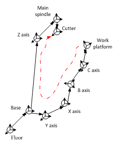
Kinematic Chain Example
The following figure shows a kinematic chain of a non-orthogonal 5-axis machine tool:
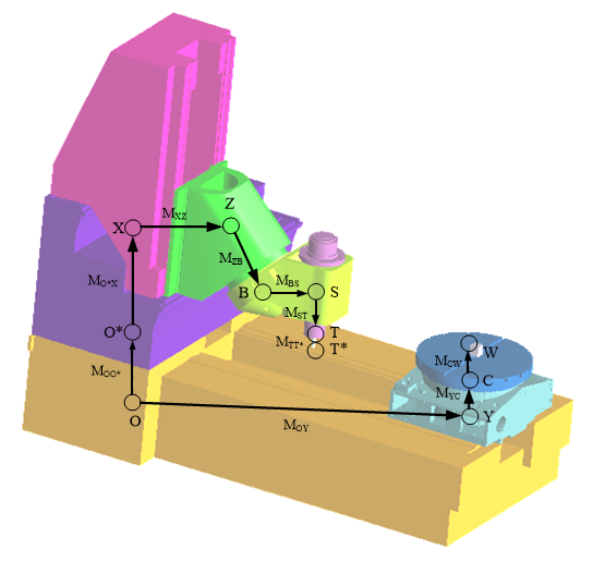
Each Anchor represents a component:
- Axis components: X, Y, Z, B, C
- Base components: O (base1), O* (base2)
- Tool components: S (spindle), T (tool body), T* (tool flute)
- Workpiece: W
The relative transform between two Anchors is calculated by multiplying the transform matrices along the Branch. For example, the transform matrix from W to T is:
This matrix can be obtained using GetMat4d(IGetAnchor, IGetAnchor).