Mesh Resolution
MachiningResolution_mm is the edge length of the cubes the workpiece is built from, and it is the single largest lever on how long a simulation takes. It is also the setting most often set once and forgotten, which is expensive in both directions: too fine and a run that should take minutes takes hours, too coarse and a feature the program is supposed to cut is not there to be cut.
Choosing a Value
Work coarse first. An early run answers questions — does the path collide, is the force roughly where it should be, does the optimizer have room — that do not need a fine mesh, and it answers them in a fraction of the time. Refine only for the final optimization pass, where the geometry that comes out is the deliverable.
As a planning figure, a simulation run takes somewhere between 2% and 150% of the actual machining time, spanning that whole range depending on the mesh and the step count. That is wide because it is genuinely a choice, not a property of the machine.
Where the time actually goes, and which of the two costs is currently the bottleneck, is in CPU Usage During Simulation. The short version: at the fine resolutions real NC work needs, geometry removal dominates and a finer mesh is much slower; once the mesh is coarse enough that removal is cheap, the per-step costs dominate and coarsening further buys nothing.
What Value You Actually Get
The number you type is a request, not the width. The workpiece is carved out of a cube grid that starts from one fixed root cube and is halved level by level, so every width the engine can actually build is a power of two in millimetres:
... 2 - 1 - 0.5 - 0.25 - 0.125 - 0.0625 - 0.03125 ...
A request that is not one of those is rounded to the next finer one, never to a coarser one, so the mesh you get is never worse than the mesh you asked for. The consequence worth knowing is that a value chosen off the ladder buys nothing:
| Requested | Actually built |
|---|---|
| 0.5 | 0.5 |
| 0.4 | 0.25 |
| 0.3 | 0.25 |
| 0.25 | 0.25 |
| 0.2 | 0.125 |
| 0.125 | 0.125 |
0.4 mm and 0.25 mm produce the same mesh, at the same cost. 0.4 is 0.25 wearing a misleading label: it reads as a coarse, cheap setting and runs as a fine, expensive one. If 0.25 mm is finer than the run needs, the next value that changes anything is 0.5 mm — and going the other way, 0.125 mm is another eight times the voxels, not a small step.
The ladder bottoms out at 0.001953125 mm. A finer request is clamped to it, so the finest entry offered in the workpiece's Initial Resolution list builds the same mesh as the one above it.
Pick from the ladder and the number shown in the mission row is the number the run used. That matters beyond tidiness: a recorded mesh is built at whatever resolution is in force when the record runs, so an off-ladder value is silently baked into the cache as its rounded neighbour.
What the Mesh Does Not Change
For a representative test case — downward circular slot milling with varying width and depth — the physical values move within about 20% across the full range of mesh widths. The simulated forces, torques and temperatures from a coarse first pass are therefore already informative; they do not become a different answer when the mesh is refined.
The visible geometry is a different matter, and it is what the three runs below show. Workpiece 70 × 50 × 50 mm:
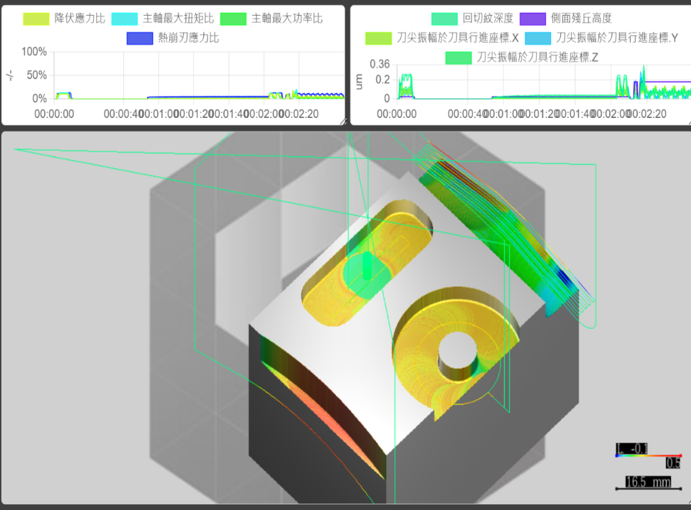 Mesh width 0.125 mm
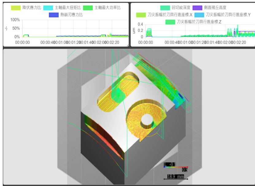 Mesh width 0.5 mm
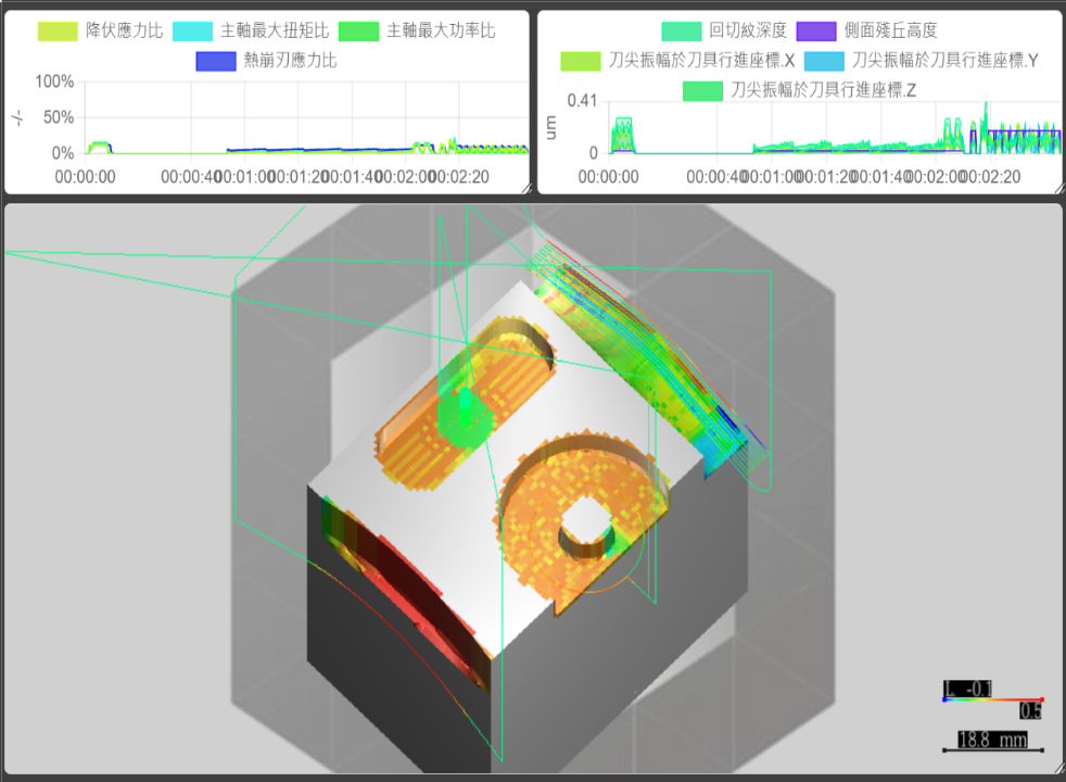 Mesh width 1 mm
The Failure Mode Worth Knowing
A thin shell thinner than the mesh width can disappear entirely. The test case above has no thin shell, which is why its physical values are so insensitive; a part that does have one behaves differently, because the material the cutter should be meeting is not represented at all. Where the workpiece has a wall, web or floor thinner than the mesh width, the mesh must be finer than that feature before the run says anything about it.
The related and much smaller effect is quantization ripple in the per-step ratios, which a finer mesh reduces — see Process Machinability.
See Also
- CPU Usage During Simulation — which of the two cost drivers a given mesh width puts in the way
- Process Machinability — the mesh-quantization ripple in the availability ratios, and why it is an artifact rather than a signal
- Workpiece — where the initial resolution is set, on the branch carrying the stock it applies to